20140814 - Lesson 12 and 13 (Movement Sensing and Power Control)
The lesson this week will be using a pIR sensor, and a magnetic reed switch to display on the screen On/Off conditions. The 2nd part of the lesson will take what we learned from Lesson 12 and use the pIR sensor to turn on a outlet (or in our case a light bulb).
So to start off we need a pIR sensor, Magnetic reed switch, breakout board, breadboard, relay, batteries, a light bulb, and of course the Raspberry Pi.
The important thing to take away from Lesson 12 is how to activate the built in Pull-UP resistor for use with the reed-switch. Which is this code:
io.setup(door_pin, io.IN, pull_up_down=io.PUD_UP)
The pIR’s output is 3.3v volt and doesn’t need a pull-up because it is digital.
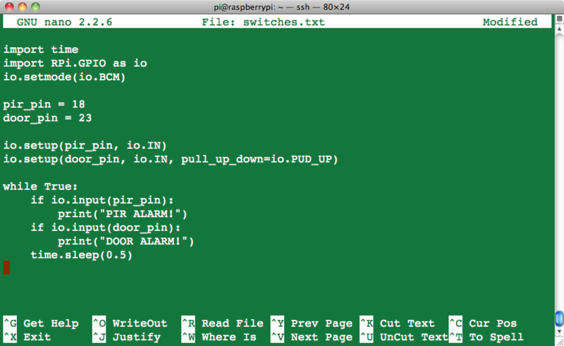
So what else does the code say to do?
It will display the words: “PIR ALARM!” or “DOOR ALARM” if either one are triggered.
pretty simple and straightforward.
remember to run the program you need to execute it with the sudo command:
sudo python switches.py
Once that works, you might asked what good is that going to do? Well, how about turning a light on for a period of time and turning it off again.
Lesson 13 is just that - using the pIR sensor and a relay we can turn on a light, the light will remain on for 20 seconds and turn off and wait for motion again.
Really, You could use the reed switch to do the same thing, think about a closet with a bulb in it, you want it on while the door is open, if you forget to close the door the light will shut it’s self off, of course the code would need to be changed to not trigger again because the door was still open. (anyways, that is just a thought)
In this lesson Adafruit uses something called a “Power Switch Tail 2” https://www.adafruit.com/products/268
This looks like a 110v extension of a outlet. It is really a controllable opto-ilsolated solid-state relay. On one side you have the high AC voltage (110v) on the other side you have a low 3.3v (5v) that when it goes high will turn on the AC voltage.
For this demo, I’m just going to use a common relay - my realy can handle 110v AC, but for now I’m just going to use 6 volts DC on one side, and 3.3v on the other. My relay is also a mechanical relay. Also it works just the opposite of the the “Tail” in that a low will activate my relay, so the code needs to be changed slightly for me.
This is the code from Adafruit. The code I used is the same making all the True to False, and all the False to True
|
I also changed the pir_pin and power_pin because I had it all on the same breadboard, and didn’t make changes to the circuit.
So you can probably see some how this works already, but after the setup, and letting the Pi know if the pins will be input or output, the program waits for the pIR to trigger, it then activates the relay, the light will stay on for 20 seconds, it also displays on the screen that the power is on, after 20 seconds, it displays off, and turns off the relay - it waits for a total of 6 seconds before asking if the pIR has triggered again.
Why does it wait? It helps to prevent immediate retriggering - if your relay is clicking a lot, you may need to increase this wait time.
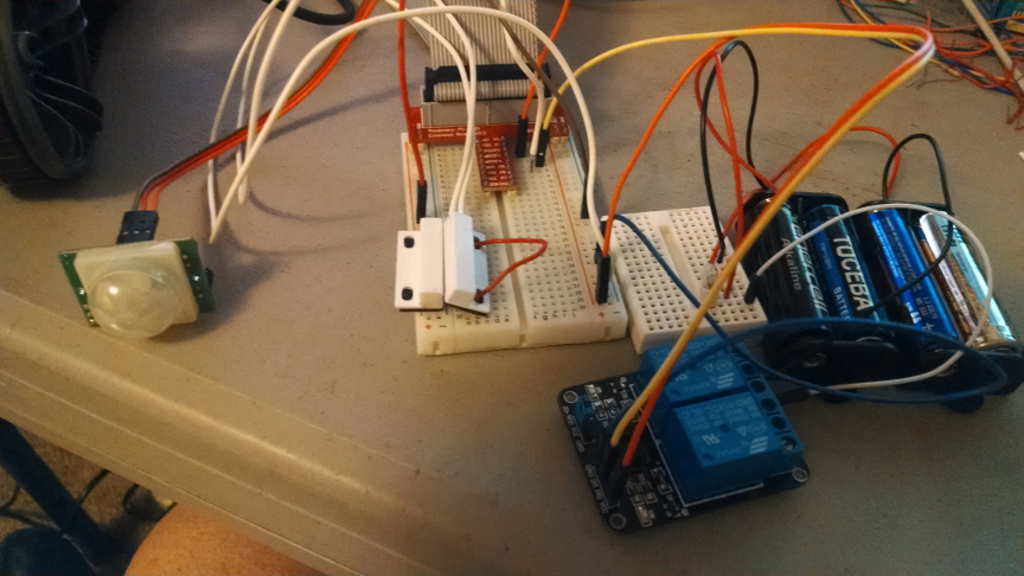
My final circuit was mounted to a board, which I didn’t take a picture of, but other then how it was mounted, this is the same.
Next week we start some basics with the Beaglebone Black.
Aug 14, 2014 - Lesson 12 and 13 (Movement Sensing and Power Control)
The lesson this week will be using a pIR sensor, and a magnetic reed switch to display on the screen On/Off conditions. The 2nd part of the lesson will take what we learned from Lesson 12 and use the pIR sensor to turn on a outlet (or in our case a light bulb).
So to start off we need a pIR sensor, Magnetic reed switch, breakout board, breadboard, relay, batteries, a light bulb, and of course the Raspberry Pi.
The important thing to take away from Lesson 12 is how to activate the built in Pull-UP resistor for use with the reed-switch. Which is this code:
io.setup(door_pin, io.IN, pull_up_down=io.PUD_UP)
The pIR’s output is 3.3v volt and doesn’t need a pull-up because it is digital.
So what else does the code say to do?
It will display the words: “PIR ALARM!” or “DOOR ALARM” if either one are triggered.
pretty simple and straightforward.
remember to run the program you need to execute it with the sudo command:
sudo python switches.py
Once that works, you might asked what good is that going to do? Well, how about turning a light on for a period of time and turning it off again.
Lesson 13 is just that - using the pIR sensor and a relay we can turn on a light, the light will remain on for 20 seconds and turn off and wait for motion again.
Really, You could use the reed switch to do the same thing, think about a closet with a bulb in it, you want it on while the door is open, if you forget to close the door the light will shut it’s self off, of course the code would need to be changed to not trigger again because the door was still open. (anyways, that is just a thought)
In this lesson Adafruit uses something called a “Power Switch Tail 2” https://www.adafruit.com/products/268
This looks like a 110v extension of a outlet. It is really a controllable opto-ilsolated solid-state relay. On one side you have the high AC voltage (110v) on the other side you have a low 3.3v (5v) that when it goes high will turn on the AC voltage.
For this demo, I’m just going to use a common relay - my realy can handle 110v AC, but for now I’m just going to use 6 volts DC on one side, and 3.3v on the other. My relay is also a mechanical relay. Also it works just the opposite of the the “Tail” in that a low will activate my relay, so the code needs to be changed slightly for me.
This is the code from Adafruit. The code I used is the same making all the True to False, and all the False to True
|
I also changed the pir_pin and power_pin because I had it all on the same breadboard, and didn’t make changes to the circuit.
So you can probably see some how this works already, but after the setup, and letting the Pi know if the pins will be input or output, the program waits for the pIR to trigger, it then activates the relay, the light will stay on for 20 seconds, it also displays on the screen that the power is on, after 20 seconds, it displays off, and turns off the relay - it waits for a total of 6 seconds before asking if the pIR has triggered again.
Why does it wait? It helps to prevent immediate retriggering - if your relay is clicking a lot, you may need to increase this wait time.
My final circuit was mounted to a board, which I didn’t take a picture of, but other then how it was mounted, this is the same.
Next week we start some basics with the Beaglebone Black.
UPDATE: Apr 7, 2015 - This demo was done about a year ago, it was with A Raspberry PI B - since doing this, there have been additions to Raspberry PI - such as the B+, and B 2 (It's being offered for Historical reasons)
No comments:
Post a Comment